DIY Simple Door Security alarm System Circuit Diagram Creating an alarm circuit is key to stopping theft. It needs a careful circuit design process. This part talks about the main steps to design an alarm circuit. It also covers using breadboarding techniques for testing and making changes. Step-by-Step Circuit Design Process. To make a good alarm circuit, follow these steps:

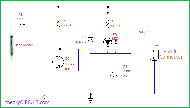
The Simple Door Security Alarm Circuit is a circuit that is designed to produce a beep and light up a LED when a person hits the door handle from outside. The circuit is encapsulated in a compact plastic or timber container. It must be hung up to the door handle using a thick cable link overhanging from the container's apex.

Build Your Own Alarm Circuit Easy and Practical Alarm Circuit ... Circuit Diagram
In this video, we create a simple alarm circuit that anyone can make at home! With this basic alarm circuit, you can take your first step into the world of e When it comes to enhancing home security, few projects are as rewarding and educational as creating a simple alarm circuit. Whether you're a seasoned electronics enthusiast or just starting your journey into the world of beginner electronics , building a DIY alarm system can be a fulfilling experience.

Understanding Alarm Circuits: A Simple Circuit Diagram. An alarm circuit is an electronic device that is designed to detect and alert individuals to the presence of a specific condition or event. This can include things like a fire alarm, a burglar alarm, or even a simple alarm clock. In this article, we will focus on a simple alarm circuit
Easy Home Security DIY - YouTube Circuit Diagram
Important Post: Pull Pin Security Alarm Circuit. Working of Security Alarm Circuit: S1 and S2 are the two switches that are used in the circuit so that both can be put in two different places i.e. one of them can put in front of the locker while another one can be placed on the front door. When the switch S1 is pressed diode D1 which is linked